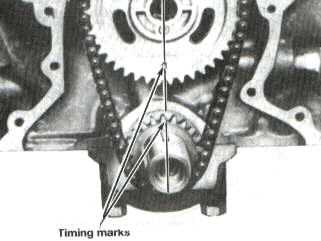
87-95 Mustang Timing Cam to Crank Alignment
Check Camshaft Cam Alignment
In order to check cam timing, you will need some specialty tools. You will need a degree wheel, dial indicator with magnetic base and a heavy wire for a timing pointer. Choose a large diameter wheel as they are easier to read and more durable. Some manufacturers sell kits with a rigid, adjustable pointer that mounts easily to the front of the engine. The other option is a heavy wire that is mounted to the block and bent into position.
Start with placing the dial indicator and stand on the right side block deck to measure travel of the CENTER of piston number 1 (passenger side, front). Bring number 1 to TDC (Top Dead Center) by observing when the dial indicator stops moving. Bolt the degree wheel to the front of the crankshaft, and attach the pointer to the front of the block so that the pointer is positioned at the zero degree reading on the wheel. To find exact TDC, first set the dial indicator to zero at the point of highest piston travel. Next, turn the crankshaft counterclockwise about 90 degrees. Then, slowly rotate the crankshaft clockwise (the normal direction of engine rotation) until the indicator is .030″ below the TDC (zero) setting. Note the reading of the degree wheel at this point. Then, continue turning the crankshaft clockwise past the TDC about 90 degrees. Slowly rotate the crankshaft backwards counterclockwise until the same .030″ below TDC is seen on the dial indicator. Again, note the degree wheel reading. Next, rotate the degree wheel so the pointer falls at the AVERAGE of the two observed readings. Lastly, relocate the pointer exactly over the zero reading of the
degree wheel, and you will have perfectly dialed in TDC. Redo the procedure to satisfy yourself that the setting is correct, and then proceed to measure cam timing.
Install the number 1 cylinder intake lifter in the proper lifter bore. Position the dial indicator so the tip is on the edge of the lifter or in the center of the lifter. Extensions for the dial indicator may be necessary. Carefully line up the dial indicator so the travel of the indicator is linear to the lifter. Rotate the engine and observe the action of the lifter. Make sure the fully open and fully closed positions of the lifter are within the travel range of the dial indicator. Rotate the crankshaft until the lifter is at the highest point of its travel, and set the dial indicator to zero. Continue rotating the engine clockwise until the lifter starts to travel up again. Slowly continue until the lifter is .030″ below the point of maximum travel, and note the reading of the degree wheel.
Start rotating the crank again until the lifter is .030″ below the maximum travel on the closing side of the cam lobe. Note the degree wheel reading. The AVERAGE of the two readings taken is the location of maximum intake lift ATDC (After Top Dead Center). Compare this to the installation recommendation of the cam manufacturer, as it should be relatively close. The timing should be within one degree of the recommended setting. If there is a need to adjust the timing, FRPP has multi-index timing chain sets which have nine keyways to adjust cam timing. NOTE: Many cam manufacturers provide .050″ lift cam timing information. To check this, reset the dial indicator to zero with the lifter at zero lift. Then rotate the crank in the clockwise direction until .050″ lift is shown on the indicator. Note the intake open degrees. Then proceed clockwise until the intake closing at .050″ lift is reached. Compare the readings to the cam card. Together with the maximum lift information, this data will tell you where the cam is degreed. Once corrections are made, measure the cam timing once more to verify the fix was correct.
