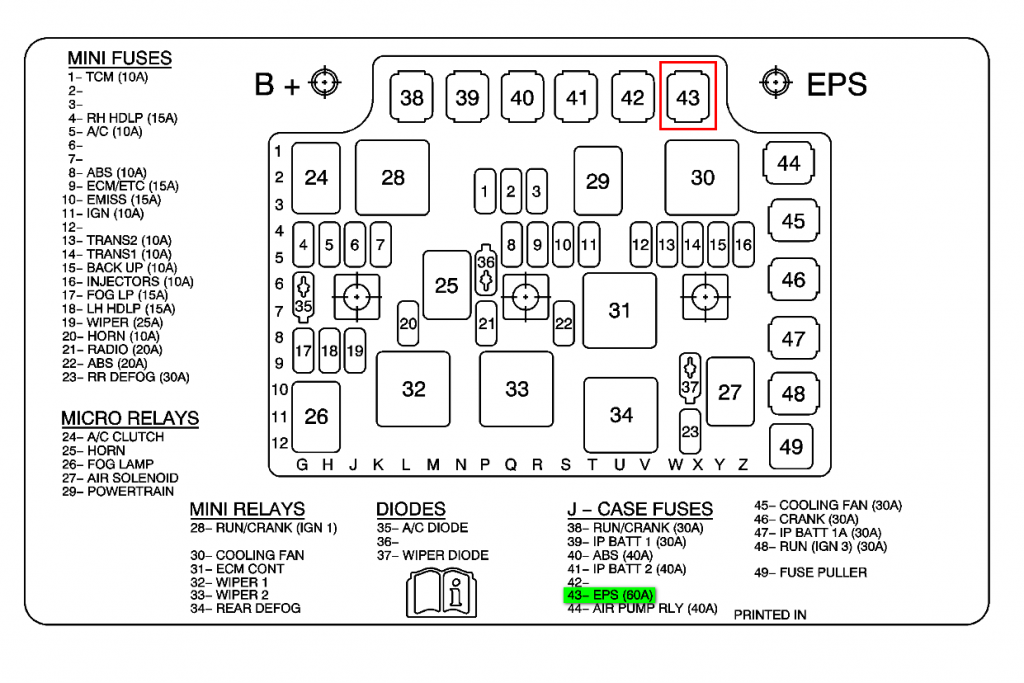
2003-2004 Saturn ION Fuse Box Diagram located under the hood in the engine bay on the drivers side.

| Fuses | Usage | |
| 1 | ECM | Engine Control Module |
| 4 | RH HDLP | Passenger’s Side Headlamp |
| 5 | A/C | Air Conditioning Clutch Relay |
| 8 | ABS | Anti-lock Brake System |
| 9 | ECM/ETC | Engine Control Module |
| 10 | EMISS | Canister Purge Solenoid, Mass Air Flow Sensor, Low Coolant Switch, Oxygen Sensors |
| 11 | IGN | Ignition Coils (1,2,3,4) |
| 13 | ECM | Engine Control Module |
| 14 | BOOST | Engine Boost Solenoid |
| 15 | BACK-UP | Back-up Switch |
| 16 | INJECTORS | Fuel Injectors (Cylinder 1, 2, 3, 4) |
| 18 | LH HDLP | Driver’s Side Headlamp |
| 19 | WIPER | Wiper Mini Relay |
| 20 | HORN | Horn Micro Relay |
| 21 | RADIO | Radio |
| 22 | ABS | Anti-lock Brake System |
| 23 | RR DEFOG | Rear Defog Mini Relay |
| 38 | RUN/CRANK | Ignition 1 Mini Relay |
| 39 | IP BATT1 | Body Control Module |
| 40 | ABS | Anti-lock Brake System |
| 41 | IP BATT2 | Body Control Module |
| 43 | EPS | Electric Power Steering |
| 44 | COOLING FAN 2 | Cooling Fan Mini Relay |
| 45 | COOLING FAN 1 | Cooling Fan Mini Relay |
| 46 | CRANK | Crank |
| 47 | IP BATT 1A | Body Control Module |
| 48 | RUN (IGN 3) | Body Control Module |
| Relays | Usage | |
| 24 | A/C CLUTCH | Air Conditioning Clutch |
| 25 | HORN | Horn |
| 27 | AFTER COOLER PUMP | After Cooler Pump |
| 28 | RUN/CRANK | Body Control Module |
| 29 | POWERTRAIN | Powertrain |
| 30 | COOLING FAN 1 | Engine Cooling Fan |
| 31 | ECM CONT | Starter Solenoid |
| 32 | WIPER1 | Wiper System |
| 33 | WIPER2 | Wiper System |
| 34 | REAR DEFOG | Rear Window Defogger |
| Diodes | Usage | |
| 35 | A/C | Air Conditioning Diode |
| 37 | WIPER | Wiper Diode |